
Assembly

Electronics

Software

OVERVIEW
So, you have decided to build a robot? Cool beans, we would love to help. After a quick download and a lot of printing, you will be ready to build your very own MAKI. The following guide will cover recommended tools, the BOM, electrical wiring, servo configuration, Pi setup, assembly, and software setup. At this time, we only cover ARC setup for MAKI edu, but we are working on future ROS support.

TOOLS


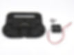
Micro USB Cable

SD Card Reader

HDMI Display

HDMI Cable

Keyboard/Mouse

Heat Gun

Shrink Tubing

Solder

Soldering Iron


Phillips Screwdriver

M3 Screwdriver

Cable Zip Ties
There are many tools which will be required to complete this project. In addition to the tools pictured below, a 3D Printer and Windows PC are necessary to create and operate a MAKI robot running ARC.
The following tools are not required, but recommended.
BOM
Below is a list of parts required to build MAKI edu. The Google AIY kit is optional because the speaker and microphone from the remote PC can be used for speech recognition and synthesis. There is also hardware which is not listed because it is included with the servos, such as the standard X3P cables and included bolts. Please read through the entire assembly process before purchasing any parts or tools.


WIRING
The following steps document how to connect cables, 2-pin connectors, the DC power jack, the rocker switch, the 4-pin connector, the voltage regulator, as well as where to solder the headers onto the OpenCM9.04 board. The connectors are optional in many cases. While connectors make assembling/disassembling a bit easier, they also add extra parts to troubleshoot if you have a power issue later.

Step 1 - Splice one 2-pin connector with two 2-pin connectors. Optionally, use a male connector for the main 2-pin connector and female connectors for the other two.
Step 2 - Connect a two pin connector to the DC power jack. Connect the positive cable to the short pin. Be sure to verify that the connector can fit through the power jack hole in the base. Optionally, you can use a different style of connector to make connectors easier to identify later.


Step 3 - Connect both negative cables from each 2-pin connector to each pin on the rocker switch. Next, connect the two positive cables together. One 2-pin connector should match the main 2-pin connector from Step 1 and the other should match the 2-pin connector from Step 2.
Step 4 - Splice together two lengths of wire to both the negative and positive cables of a 2-pin connector. Solder those four wires to each pin of a 4-pin connector. The 2-pin connector will have to match one of the two spliced 2-pin connectors from Step 1.


Step 5 - Solder a 2-pin connector to the 5V USB voltage regulator. The 2-pin connector will have to match one of the spliced 2-pin connectors from Step 1.
Step 6 - Solder the 4-pin header (to power), X3P header(s) and power switch (optional) to the OpenCM9.04 board. If you used a female 4-pin connector in Step 4, use a male 4-pin header in this step. OpenCM9.04 Manual - Powering

SERVO SETUP
MAKI uses Dynamixel servos from Robotis, a leading manufacturer of advanced robot servos. Dynamixel servos connect via daisy chain and require separate ID's to operate. Each servo ships from the factory with it's ID number set to 0, so we will have to connect and configure each servo separately.
Step 1 - Connect the power supply, SMPS2Dynamixel, X3P-Convertable Cable, one XL430 servo, X3P Cable, U2D2 and micro
USB cable.

Step 2 - Next we will assign ID's and set angle limits for each servo.
Download and install Dynamixel Wizard.
After installing, connect the USB cable to your PC and launch Dynamixel Wizard. Select "Options" and select, protocols 1.0 and 2.0 under "Select protocol to scan." Also select the correct port. Under "Select baudrate to scan," select "57600 bps" and "1000000 bps." To save scanning time, and because our robot only uses six servos; you can also set the ID range to scan, to a range of 0 - 10 (or so). Select "Okay" to close the "Options" window. Click "Scan" to find the connected servo.

Step 3 - Set the ID, Baud Rate, Max Position Limit and Min Position Limit for each servo (one servo connected at a time).


It is also recommended that you connect the OpenCM9.04 board to your PC via micro USB cable and update the firmware using Dynamixel Wizard or R+ Manager.
THREADED HEATSET INSERTS
Adding threaded heatset inserts to your 3D printed parts increases their durability and allows you to replace parts in assemblies without fear of stripping 3D printed holes when tightening screws/bolts. MAKI edu uses M3-0.5 threaded heatset inserts which are installed with a soldering iron and heatset install tip. Here is a how to guide by Joshua Vasquez on using heatset inserts.


2 x Rear Head Mount 2 L
8 x Threaded Heatset Inserts
2 x Eye 1
2 x Threaded Heatset Inserts


Neck 2 and Neck Servo Mount
8 x Threaded Heatset Inserts
Eye Servo Mount, Eye UD Mount 1, and Eye Pitch Arm
2 x Threaded Heatset Inserts


Rear Head Mount
18 x Threaded Heatset Inserts
Eye Servo Mount and Eyelid Servo Control Arm R
3 x Threaded Heatset Inserts


Neck Cover Front
4 x Threaded Heatset Inserts
Eyelid Servo Control Arm L
1 x Threaded Heatset Inserts


Camera Mount
1 x Threaded Heatset Inserts
Lower Mount Eyes
2 x Threaded Heatset Inserts


Top Eye Lid L and Eyelid Control Arm L
2 x Threaded Heatset Inserts
Top Eye Lid R and Eyelid Control Arm R
2 x Threaded Heatset Inserts


Torso Base Mount 2
15 x Threaded Heatset Inserts
AIY Microphone Mount 1
4 x Threaded Heatset Inserts


Face 1
4 x Threaded Heatset Inserts
Lower Head 1
8 x Threaded Heatset Inserts


Base Top 1 and Base Bttm 1
10 x Threaded Heatset Inserts
2 x Ear 1
8 x Threaded Heatset Inserts
ASSEMBLY NECK
The following section will cover the Neck Assembly.
Tips - Each servo should already be configured before proceeding. Different 3D printers and materials produce different tolerances and finishes. It is a good idea to check the fit before your final assembly. It maybe required to sand some parts for the best fit. Deburring tools are also useful for creating smooth rotation between two 3D printed parts. Zero servos before assembling.


Step 1
Neck Cover 1 - Neck Servo Mount - 2x Neck Spacers - XL430 Servo (ID 1) - X3P Cable - X3P (Convertible) Cable
Tips: It is possible to use 3D printed parts for the two Neck Spaces, but for best results, laser cut or CNC the Neck Spacers from a material like Delrin or Acetal Copolymer.
Step 2
Neck 1 - XL430 Servo (ID 2) - X3P Cable
Tips: After removing the four screws located on the back of the servo, insert the four spacers (included with the servo) into the servo before attaching it to Neck 1.


Step 3
Assembly from Step 1 - Assembly from Step 2 - Neck 2 - Raspberry Pi Ribbon Cable
Tips: Carefully run the cables on each side of the servo before assembling. The ribbon cable should be placed on the left side of the servo (if facing servo).
Step 4
Assembly from Step 3 - Neck Head Mount L
Tips: Depending on your 3D printer and material, it maybe necessary to tap the four holes in Neck Head Mount L. Tap the holes to avoid stripping any bolts.
ASSEMBLY EYES
The following section will cover the Eye Assembly.
Tips - Each servo should already be configured before proceeding. Different 3D printers and materials produce different tolerances and finishes. It is a good idea to check the fit before your final assembly. It maybe required to sand some parts for the best fit. Deburring tools are also useful for creating smooth rotation between two 3D printed parts.


Step 5
Top Eyelid R - Eyelid Horn 1 R - Lever Hub - Eyelid Control Arm R
Tips: Depending on your 3D printer and material, it maybe necessary to sand and/or deburr the points of contact in this assembly.
Step 6
Top Eyelid L - Eyelid Horn 1 L - Lever Hub - Eyelid Control Arm L
Tips: Depending on your 3D printer and material, it maybe necessary to sand and/or deburr the points of contact in this assembly.

ASSEMBLY - HEAD - Part 2

Step 7
Eyes Top Mount - XL430 servo (ID 4)
Tips: After removing the four screws located on the back of the servo, insert the four spacers (included with the servo) into the servo before attaching it to Eyes Top Mount.
Step 8
Eyes LR Horn
Tips: Remove any support material from the hole seat. The head of the bolt should sit flush with the printed part's surface.


Step 9
Eye Servo Mount - XL430 servo (ID 5) - Eyelid Servo Control Arm L - Eye UD Mount 1 - X3P Cable
Tips: After removing the four screws located on the back of the servo, insert the four spacers (included with the servo) into the servo before attaching it to Eye Servo Mount.
Step 10
Assembly from Step 9 - Eyes UD Lever - Lever Hub
Tips: Depending on your 3D printer and material, it maybe necessary to sand and/or deburr the points of contact in this assembly.


Step 11
Eye Servo Mount - XL430 servo (ID 6) - Eyelid Servo Control Arm R - 2x X3P Cables
Tips: After removing the four screws located on the back of the servo, insert the four spacers (included with the servo) into the servo before attaching it to Eye Servo Mount.
Step 12
Assembly from Step 7 - Assembly from Step 8
Tips: Do not overtighten the bolts in the servo horn. After attaching the Eyes LR Horn, gently rotate left and right to make sure the horn moves freely.


ASSEMBLY - HEAD - Part 2
Step 13
Assembly from Step 10 - Assembly from Step 11 - Assembly from Step 12
Tips: Connect one X3P cable from Servo ID 6 to Servo ID 4. Connect one X3P cable from Servo ID 6 to Servo ID 5.
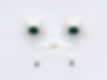
Step 14
2x Eyes 1 - 2x Iris 1 - 2x Pupil 1
Tips: These two eyes can be assembled with glue or screws. There is also version of this eye which uses 25mm plastic safety eyes.

Step 15
Assemblies from Step 12 - Eyes LR Lever 1 - 2x Lever Hubs
Tips: Depending on your 3D printer and material, it maybe necessary to sand and/or deburr the points of contact in this assembly.
Step 16
Assembly from Step 13 - Assembly from Step 15 - Lower Mount Eyes
Tips: Depending on your 3D printer and material, it maybe necessary to sand and/or deburr the points of contact in this assembly.

Step 17
Assembly from Step 16 - Eye Face Mount L - Eye Face Mount R
Tips: Depending on your 3D printer and material, it maybe necessary to sand and/or deburr the points of contact in this assembly.
Step 18
Assembly from Step 5 - Assembly from Step 6 - Assembly from Step 17
Tips: Depending on your 3D printer and material, it maybe necessary to sand and/or deburr the points of contact in this assembly..
ASSEMBLY HEAD
The following section will cover the Head Assembly.
Tips - Each servo should already be configured before proceeding. Different 3D printers and materials produce different tolerances and finishes. It is a good idea to check the fit before your final assembly. It maybe required to sand some parts for the best fit. Deburring tools are also useful for creating smooth rotation between two 3D printed parts.


Step 19
Assembly from Step 3 - Eye Face Mount R - Lower Head 1 - Steel Shaft
Tips: Depending on your 3D printer and material, it maybe necessary to tap the hole in Eye Face Mount R before inserting the Steel Shaft.
Step 20
Neck Front Cover - 2x Rear Head Mount - Camera Mount
Tips: Depending on your 3D printer and material, it maybe necessary to sand parts to achieve the best fit.


Step 21
Assembly from Step 19 - Assembly from Step 20
Tips: Depending on your 3D printer and material, it maybe necessary to sand parts to achieve the best fit.
Step 22
Assembly from Step 21 - Neck Cover Servo Mount
Tips: Depending on your 3D printer and material, it maybe necessary to sand parts to achieve the best fit.


Step 23
XL430 Servo (ID 3) - Eyes UD Horn
Tips: Do not overtighten the bolts in the servo horn. After attaching the Eyes LR Horn, gently rotate left and right to make sure the horn moves freely.
Step 24
Assembly from Step 22 - Assembly from Step 23
Tips: After removing the four screws located on the back of the servo, insert the four spacers (included with the servo) into the servo before attaching it to Neck Servo Mount.


Step 25
Assembly from Step 18 - Assembly from Step 24 - Eyelid Center Mount - 3/16" x 3/4" Aluminum Unthreaded Spacer
Tips: Depending on your 3D printer and material, it maybe necessary to sand and/or deburr parts to achieve the best fit.
Step 26
Assembly from Step 25 - Rear Head Mount
Tips: Depending on your 3D printer and material, it maybe necessary to sand and/or deburr parts to achieve the best fit.


Step 27
Assembly from Step 26 - 2x Eye Face Mount 2
Tips: Depending on your 3D printer and material, it maybe necessary to sand and/or deburr parts to achieve the best fit and smooth rotation.
Step 28
Raspberry Pi Camera - Camera Mount 2
Tips: Depending on your 3D printer and material, it maybe necessary to tap the three holes in Camera Mount 2. Tap the holes to avoid stripping any screws.


Step 29
Assembly from Step 27 - Assembly from Step 28
Tips: Depending on your 3D printer and material, it maybe necessary to tap the two holes in Camera Mount 1. Tap the holes to avoid stripping any screws.
Step 30
Assembly from Step 29 - 2x Ear 1 - 2x Ear 2
Tips: Depending on your 3D printer and material, it maybe necessary to sand parts to achieve the best fit. *The ears were design to each fit a 66mm 24 Bit LED ring inside.


Step 31
Assembly from Step 30 - Face 1
Tips: Make sure that the camera is centered on the "mouth" opening. Depending on your 3D printer and material, it maybe necessary to sand parts to achieve the best fit.
Step 32
Assembly from Step 31 - Head 1
Tips: Check that all servos are connected before closing the head. Depending on your 3D printer and material, it maybe necessary to sand parts to achieve the best fit.
ASSEMBLY BODY
The following section will cover the Body Assembly.
Tips - Each servo should already be configured before proceeding. Different 3D printers and materials produce different tolerances and finishes. It is a good idea to check the fit before your final assembly. It maybe required to sand some parts for the best fit. Deburring tools are also useful for creating smooth rotation between two 3D printed parts.


Step 33
Assembly from Step 32 - Torso Base Mount 2 - Neck Servo Mount 2 - X3P Cable (Convertible) from Step 1
Tips: Servo (ID 1) should fit securely with no play between Torso Base Mount 2 and Neck Servo Mount 2.
Step 34
Assembly from Step 33 - Micro SD to SD Card Extension
Tips: Make sure that the SD card reader is facing right side up when level with the bottom of Torso Base Mount 2.


Step 35
Assembly from Step 34 - Raspberry Pi 3 B+ - Micro USB to USB Cable - Panel Mount USB Cable
Tips: Plug the Card Extension into the micro SD port of the Raspberry Pi before mounting it to Torso Base Mount 2.
Step 36
Assembly from Step 35 - Base Top 1 - DC Jack Cable - Power Switch Cable
Tips: Only partially insert the Power Rocker Switch before attaching the assembly from Step 35 to Base Top 1. This prevents over bending the Power Switch Cable.


Step 37
Assembly from Step 36 - OpenCM9.04 - 2x Zip Ties
Tips: Plug the micro USB cable into the micro USB port of the OpenCm9.04 board before mounting it to the back of Neck Servo Mount 2.
Step 38
Assembly from Step 37 - Neck Back Mount 2
Tips: Depending on your 3D printer and material, it maybe necessary to sand parts to achieve the best fit. Neck Servo Mount should rotate smoothly.

Step 39
Microphone Mount 1 - Voice Hat Microphone Board - 5 Wire Daughter Board Cable
Tips: The AIY Voice Kit is optional, but a great addition. Review the Assembly Guide and User Guide to use the AIY Voice Kit as an embedded smart speaker for MAKI.
Step 40
Assembly from Step 38 - Assembly from Step 39
Tips: Depending on your 3D printer and material, it maybe necessary to sand parts to achieve the best fit.

Step 41
Base Bttm 1 - 5V PC Fan
Tips: Depending on your 3D printer and material, it maybe necessary to sand parts to achieve the best fit.
Step 42
AIY Bttn Mt 1 - Button Harness - Push Button
Tips: Depending on your 3D printer and material, it maybe necessary to sand and/or deburr parts to achieve the best fit.


Step 43
Assembly from Step 40 - 4-Pin Connector Cable - Voltage Regulator Cable - Angled Micro USB Cable
Tips: Connect the the 2-pin connectors from the 4-Pin Connector Cable and the Voltage Regulator Cable to the spiced 2-pin connectors from Wiring Step 1.
Step 44
Assembly from Step 43 - Voice HAT Accessory Board
Tips: The AIY Voice Kit is optional, but a great addition. Review the Assembly Guide and User Guide to use the AIY Voice Kit as an embedded smart speaker for MAKI.


Step 45
Assembly from Step 42 - Assembly from Step 44 - 3" Speaker - Panel Mount HDMI Cable
Tips: The AIY Voice Kit is optional, but a great addition. Review the Assembly Guide and User Guide to use the AIY Voice Kit as an embedded smart speaker for MAKI.
Step 46
Assembly from Step 41 - Assembly from Step 45
Tips: The SD card reader should fit securely with no play between Body Top 1 and Body Bttm 1.


Step 47
Body F 1 - Speaker Cover 1 - Speaker Grill Cloth (Optional)
Tips: Stretch the Speaker Grill Cloth over the Speaker Cover and insert it into Body F 1. Trim the excess material with a small pair of scissors.
Step 48
Assembly from Step 46 - Assembly from Step 47
Tips: Place the assembly from Step 42 (Push Button) in the left space of Torso Base Mount 2 before attaching Body F 1 to Torso Base Mount 2.


Step 49
Assembly from Step 48 - Body B 1
Tips: Depending on your 3D printer and material, it maybe necessary to sand parts to achieve the best fit.
Step 50
Assembly from Step 49
Tips: Do not overtighten bolts when attaching the HDMI panel mount to Body B 1. The threading in the mount is easy to strip.

Step 51
Assembly from Step 50
Tips: Depending on your 3D printer and material, it maybe necessary to sand parts to achieve the best fit.
SOFTWARE SETUP
ARC is a "user-friendly autonomous robot control software for programming robotics, fast." - Synthiam
In this configuration of MAKI edu, we will install EZB Server onto a Raspberry Pi and install ARC on a Windows PC. This will allow us to connect to and control MAKI remotely, via WiFi. We have prepared an SD card image which already has Raspberry Pi operating system, EZB Server and Google AIY installed and
Step 1 - Download the latest version of ARC here.
Setup an account and follow the installation steps provided by Synthiam.
Step 2 - Download the latest MAKI edu EZ-Builder Project file, available here.
Place the downloaded EZ-Builder Project file into your \ARC\My Projects\ folder. This folder was created when you installed ARC.
Step 3 - Install Raspberry Pi operating system image on an SD card.
Download and install the latest version of Raspberry Pi Imager, found here. The Raspberry Pi Foundation also provides instructions on installing the image to the SD card.
Step 4 - Install EZB Server (Blueberry Server) onto Raspberry Pi.
Provided by Pedro Pereira, Blueberry Server turns a Raspberry Pi into an EZ-B V4. Detailed instructions on installing Blueberry Server can be found here.
Step 5 - Install opencm USB port settings (Point: 8.3.1.1)
Source: http://emanual.robotis.com/docs/en/parts/controller/opencm904/
Run the following four lines in the Raspberry Pi terminal window:
Code:
Step 6 - You can now confirm that the OpenCM9.04 is available.
Code:
You should see the serial device: /dev/ttyACM0
Step 7 - Update your Blueberry Server repository.
Code:
The last command updates your local repository.
Step 8 - Start the Blueberry Server.
Use opencm as serial uart0 and picamera.
Code:
Step 9 - Launch ARC on PC and connect to robot.
Open MAKI edu EZ-Builder Project file.
python3 Main.py --uart0=/dev/ttyACM0 --camtype=picamera
cd ~/BlueberryServer (or whatever location) git pull
ls /dev/ttyA*
wget https://raw.githubusercontent.com/ROBOTIS-GIT/OpenCM9.04/master/99-opencm-cdc.rules
sudo cp ./99-opencm-cdc.rules /etc/udev/rules.d/
sudo udevadm control --reload-rules
sudo udevadm trigger

Click on the "antenna" icon in the Connection window (connection 0). This will scan for the EZB Server.
Select: raspberrypi-Server (xx.x.x.xxx:xxxxx) (Type:EZ-B)

Click on the "antenna" icon in the Video Device window. This will scan for the Raspberry Pi camera which is connected to the EZB Server (Raspberry Pi).
Select: raspberrypi-Server (xx.x.x.xxx:xxxxx) (Type:Camera)
Congrats! Now you are ready to control your MAKI edu robot. Synthiam provides excellent support and documentation for getting started with their software.